
Secret encoders
In addition to the two approaches described above, many other methods for selecting appropriate candidate motion vectors exist, including a wide variety of proprietary solutions. Most video compression standards specify only the format of the compressed video bit stream and the decoding steps and leave the encoding process undefined so that encoders can employ a variety of approaches to motion estimation. The approach to motion estimation is the largest differentiator among video encoder implementations that comply with a common standard. The choice of motion estimation technique significantly affects computational requirements and video quality; therefore, details of the approach to motion estimation in commercially available encoders are often closely guarded trade secrets.
Motion compensation
I n the video decoder, motion compensation uses the motion vectors encoded in the compressed bit stream to predict the pixels in each macro block. If the horizontal and vertical components of the motion vector are both integer values, then the predicted macro block is simply a copy of the 16-pixel by 16-pixel region of the reference frame. If either component of the motion vector has a non-integer value, interpolation is used to estimate the image at non-integer pixel locations. Next, the prediction error is decoded and added to the predicted macro block in order to reconstruct the actual macro block pixels. As mentioned earlier, the 16×16 macro block may be subdivided into smaller sections with independent motion vectors.
Compared to motion estimation, motion compensation is much less computationally demanding. While motion estimation must perform SAD or SSD computation on a number of 16-pixel by 16-pixel regions in an attempt to find the best match for each macro block, motion compensation simply copies or interpolates one such region for each macro block. Still, motion compensation can consume as much as 40% of the processor cycles in a video decoder, though this number varies greatly depending on the content of a video sequence, the video compression standard, and the decoder implementation. For example, the motion compensation workload can comprise as little as 5% of the processor cycles spent in the decoder for a frame that makes little use of interpolation.
Like motion estimation, motion compensation requires the video decoder to keep one or two reference frames in memory, often requiring external memory chips for this purpose. However, motion compensation makes fewer accesses to reference frame buffers than does motion estimation. Therefore, memory bandwidth requirements are less stringent for motion compensation compared to motion estimation, although high memory bandwidth is still desirable for best processor performance.
Polishing the image: Deblocking & deranging
Ideally, lossy image and video compression algorithms discard only perceptually insignificant information, so that the reconstructed image or video sequence appears identical to the original uncompressed image or video to the human eyes. In practice, however, some artifacts may be visible. This can happen due to a poor encoder implementation, video content that is particularly challenging to encode, or a selected bit rate that is too low for the video sequence, resolution and frame rate. The latter case is particularly common, since many applications trade off video quality for a reduction in storage and/ or bandwidth requirements.
Two types of artifacts, ‘blocking’ and ‘ringing,’ are common in video compression applications. Blocking artifacts are due to the fact that compression algorithms divide each frame into 8×8 blocks. Each block is reconstructed with some small errors, and the errors at the edges of a block often contrast with the errors at the edges of neighboring blocks, making block boundaries visible. In contrast, ringing artifacts appear as distortions around the edges of image features. Ringing artifacts are due to the encoder discarding too much information in quantizing the high-frequency DCT coefficients.
Video compression applications often employ filters following decompression to reduce blocking and ringing artifacts. These filtering steps are known as ‘deblocking’ and ‘deringing’ respectively. Both deblocking and deringing use low-pass FIR (finite impulse response) filters to hide these visible artifacts.
Deblocking and deringing filters are fairly computationally demanding. Combined, these filters can easily consume more processor cycles than the video decoder itself. For example, an MPEG-4 simple-profile, level 1 (176×144 pixel, 15 fps) decoder optimized for the ARM9E general-purpose processor core requires that the processor be run at an instruction cycle rate of about 14 MHz when decoding a moderately complex video stream. If deblocking is added, the processor must be run at 33 MHz. If both deringing and deblocking are added, the processor must be run at about 39 MHz – nearly three times the clock rate required for the video decompression algorithm alone.
Post-processing or in-line
Deblocking and deringing filters can be applied to video frames as a separate post-processing step that is independent of video decompression. This approach provides system designers the flexibility to select the best deblocking and/or deringing filters for their application or to forego these filters entirely in order to reduce computational demands. With this approach, the video decoder uses each unfiltered reconstructed frame as a reference frame for decoding future video frames, and an additional frame buffer is required for the final filtered video output.
Alternatively, deblocking and/ or deringing can be integrated into the video decompression algorithm. This approach, sometimes referred to as ‘loop filtering,’ uses the filtered reconstructed frame as the reference frame for decoding future video frames. This approach requires the video encoder to perform the same deblocking and/ or deringing filtering steps as the decoder in order to keep each reference frame used in encoding identical to that used in decoding. The need to perform filtering in the encoder increases processor performance requirements for encoding, but can improve image quality, especially for very low bit rates. In addition, the extra frame buffer that is required when deblocking and/ or deringing are implemented as a separate post-processing step is not needed when deblocking and deringing are integrated into the decompression algorithm. Figure 6 illustrates deblocking and deringing applied ‘in-loop’ or as a post-processing step. H.264, for example, includes an ‘in-loop’ deblocking filter, sometimes referred to as the ‘loop filter.’
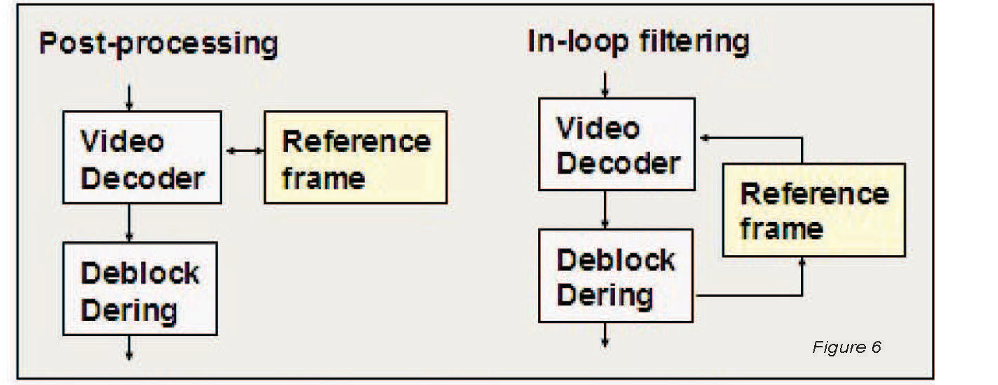
Artifacts reduction can be incorporated in the compression algorithm or applied after decoder. In post-processing deblocking/ deringing, reference frames are not filtered and the best filter for the application may be selected. With inloop filtering, in contrast, the filtered decoder output is used for the reference frames and the same filters are applied in encoder and decoder. Generally in-loop filtering results in better image quality at very low bit rates.
Color space conversion
One complication of compressing video streams is that the way color is represented in codecs is different from the way it is represented by video cameras and displays. As noted above, video compression algorithms typically represent color images using luminance and chrominance planes. In contrast, video cameras and displays typically mix red, green, and blue light to represent different colors. Therefore, the red, green, and blue pixels captured by a camera must be converted into luminance and chrominance values for video encoding, and the luminance and chrominance pixels output by the video decoder must be converted to specific levels of red, green, and blue for display. The algorithm for this conversion requires about 12 arithmetic operations per image pixel, not including the interpolation needed to compensate for the fact that the chrominance planes have a lower resolution than the luminance plane at the video compression algorithm’s input and output. For a VGA (640x480pixel) image resolution at 30 frames per second, conversion (without any interpolation) requires over 110 million operations per second. When implemented in software, this computational load can be quite significant. However, color conversion for playback is often supported by the display hardware, so it may not need to be done in software.
Know your processing & processor
Video compression algorithms employ a variety of signal-processing tasks such as motion estimation, transforms and variable-length coding. Although most modern video compression algorithms share these basic tasks, there is enormous variation among algorithms and implementation techniques. The given table summarizes the key signal-processing tasks in a video decoder and provides approximate computational load and memory requirements of each task. (Note that there can be substantial variation in these figures depending on the implementation.) As we’ve discussed, encoder requirements differ from decoder requirements in some important ways, most notably due to the inclusion of the very computationally demanding motion estimation step.
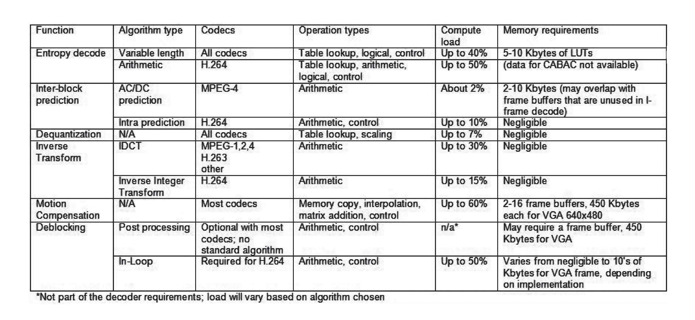
A thorough understanding of signal-processing principles, practical implementations of signal-processing functions, and the details of the target processor is crucial in order to efficiently map the varied tasks in a video compression algorithm to the processor’s architectural resources.
<- Previous | 1 | 2 | 3 | 4 | Next ->